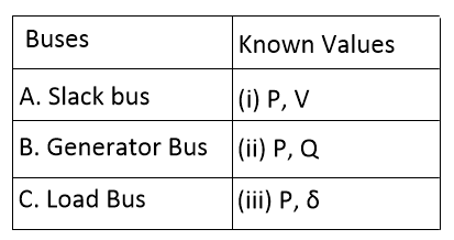
Bus Type - Known Parameter - Unknown Parameter Load Bus -P, Q - V, phase angle Generator Bus - P, V (magnitude) - Q, Voltage phase angle Slack Bus Voltage - magnitude and phase angle - P, Q
Simple logic of reactance diagram is that simplified equivalent circuit of power system in which the various components of power system are represented by their reactance. The reactance diagram can be obtained from impedance diagram if all the resistive components are neglected. So, from figure each of the component is represented by its reactance.
For t = 0 in RC circuit, After t = 0+ condition, capacitor is behave as short circuit. Voltage across the it 0. At final time, Capacitor is behave as open circuit, voltage across the capacitor at final time is equal to 15 V.
For single phase induction motor, P = VIcosφ P = 400*30*0.7 P = 8400 W Q1 = P*tan(φ) = 8400*1.020 Q = 8568.82 VAR Now power factor change to 0.9 So, φ' = 25.84 degree Q = 8400*tan(25.84) Q = 4067.95 Qnet = Q - Q' Qnet = 8568.82 - 4067.95 Qnet = 4500.8 C = V²/(2ᴨf) C = (400*400)/(2ᴨ*50) C = 8.95*10⁻⁵ C = 89.5 μF