MGVCL Exam Paper (30-07-2021 Shift 2)
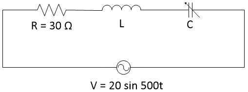
In the RLC series circuit shown in figure, resonance occurs when the value of C is 20 µF. The supply voltages is v(t) = 20 sin (500t) V. Find the value of L.
Here, ω = 500 rad/sec = 2πf. At Resonance condition, ωL = 1/(ωC) L 0.2 H Also at series resonace 1. fr = 1/[2π√(LC)] 2. PF = 1 3. Maximum current 4. Source voltage = voltage across resistor.
Simple logic of reactance diagram is that simplified equivalent circuit of power system in which the various components of power system are represented by their reactances. The reactance diagram can be obtained from impedance diagram if all the resistive components are neglected.
The main function of an interposing CT is to balance the currents supplied to the relay where there would be an imbalance due to the ratios of the main CTs. Interposing CTs are equipment with a ratio that can be selected by the user to achieve the balance required. An interposing CT is installed between the secondary winding of the main CT and relay.
When different types of consumers are charged at different uniform per unit rates, it is said to be Flat Rate Tariff. In this type, the consumers are grouped into different classes. Each class is charged at different uniform rate.