The non -uniformity in the voltage distribution over a string of suspension insulators is expressed in terms of a parameter called “string efficiency“.
The voltage across the unit nearer to the conductor is more than the voltage in the unit nearer to the support. This unequal potential distribution over the string is expressed in terms of string efficiency.
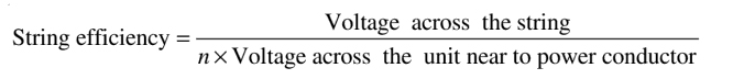
The efficiency of a string is defined as the ratio of voltage across the whole string to the product of the number of discs and the voltage across the disc nearest to the line conductor. Mathematically, it can be expressed as,
Where n = Number of the unit in the string
The more the value of the string efficiency, the more uniform is the voltage distribution across the string. For the ideal case, the string efficiency is 100% and the voltage across each disc of the string is equal. Practically various methods are used to obtain string efficiency as high as possible.