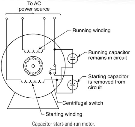
In the given diagram all are NOR Gate . The final output is shown in the figure. At stage 1 the output will be \overline A \& \overline B At stage 2 the output will be \overline {\overline A + \overline B } = A.B And the final output will be \overline {A.B} Hence for input A & B the output is \overline {AB} in case of Nand gate.
Galvanized steel conductors do not corrode, and possess high resistance. Hence such Wires are used in telecommunications circuits, earth wires, guard wire, stray wire, etc.
As you can see from the below figure in load Z1 is connected with the only current coil. In Load Z2 both current from the current coil (CC) and voltage from voltage coil (PC) are present (Power = V × I). Hence the Wattmeter will read power consumed by Z2.