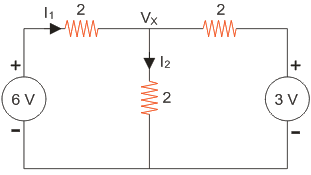
Electric Circuits In the circuit shown in figure if I1 = 1.5 A, then I2 will be 1.5 A. 2 A. 1 A. 0.5 A. 1.5 A. 2 A. 1 A. 0.5 A. ANSWER DOWNLOAD EXAMIANS APP
Electric Circuits Which of the following is the heaviest? Atom. Proton. Electron. Molecule. Atom. Proton. Electron. Molecule. ANSWER DOWNLOAD EXAMIANS APP
Electric Circuits Link in network theory refers to B - N + 1. N - 1. N - B - 1. B - N - 1. B - N + 1. N - 1. N - B - 1. B - N - 1. ANSWER DOWNLOAD EXAMIANS APP
Electric Circuits The breakdown voltage for paper capacitor is usually 2000 to 3000 volts. 20 to 60 volts. more than 10000 volts. 200 to 1600 volts. 2000 to 3000 volts. 20 to 60 volts. more than 10000 volts. 200 to 1600 volts. ANSWER DOWNLOAD EXAMIANS APP
Electric Circuits Galvanizing is the coating of chromium. lead. zinc. brass. chromium. lead. zinc. brass. ANSWER DOWNLOAD EXAMIANS APP
Electric Circuits In a delta network each element has value R. The value of each element in equivalent star network will be R / 4. R / 6. R / 2. R / 3. R / 4. R / 6. R / 2. R / 3. ANSWER DOWNLOAD EXAMIANS APP