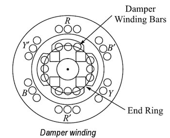
To enable the synchronous machine to start independently as a motor, a damper winding is made on rotor pole face slots. Bars of copper, aluminum, bronze or similar alloys are inserted in slots made or pole shoes as shown in Fig. These bars are short-circuited by end-rings or each side of the poles. Thus these short-circuited bars form a squirrel-cage winding. On application of three-phase supply to the stator, a synchronous motor with damper winding will start at a three-phase induction motor and rotate at a speed near to synchronous speed. Now with the application of dc excitation to the field windings, the rotor will be pulled into synchronous speed since the rotor pole are now rotating at only slip-speed with respect to the staler rotating magnetic field.
Use of Damper winding to prevent Hunting
During Hunting, the rotor of the synchronous motor starts to oscillate in its mean position, therefore, a relative motion exists between damper winding and hence the rotating magnetic field is created. Due to this relative motion, e.m.f. gets induced in the damper winding. According to Lenz’s law, the direction of induced e.m.f. is always so as to oppose the cause producing it. The cause is the hunting. So such induced e.m.f. oppose the hunting. The induced e.m.f. tries to damp the oscillations as quickly as possible. Thus hunting is minimized due to damper winding.

