Electric Circuits The voltage induced in an inductor is represented as, product of its inductance and rate of change of current through it. product of its inductance and current through it. ratio of its inductance to current through it. ratio of current through it to its inductance. product of its inductance and rate of change of current through it. product of its inductance and current through it. ratio of its inductance to current through it. ratio of current through it to its inductance. ANSWER DOWNLOAD EXAMIANS APP
Electric Circuits The capacitance of a conductor is varying from 2 microfarad to zero in 1 sec linearly if the voltage applied to it is 6 V the energy stored in 0.5 sec in the condenser is 18 µ joules. 20 µ joules. 55.1 µ joules. 10 µ joules. 18 µ joules. 20 µ joules. 55.1 µ joules. 10 µ joules. ANSWER DOWNLOAD EXAMIANS APP
Electric Circuits The energy required to charge a 10 μF capacitor to 100 V is 5 × 10⁻⁹ J. 0.05 J. 0.01 J. 10 × 10-9 J. 5 × 10⁻⁹ J. 0.05 J. 0.01 J. 10 × 10-9 J. ANSWER DOWNLOAD EXAMIANS APP
Electric Circuits A 10Ω resistor is stretched to increase its length double. Its resistance will now be 5 Ω. 10 Ω. 40 Ω. 20 Ω. 5 Ω. 10 Ω. 40 Ω. 20 Ω. ANSWER DOWNLOAD EXAMIANS APP
Electric Circuits In Cauer 1st form last element in the network is Cseries. Lseries. Lshunt. Cshunt. Cseries. Lseries. Lshunt. Cshunt. ANSWER DOWNLOAD EXAMIANS APP
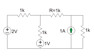
Electric Circuits The current in the resistor R shown in figure will be 0.2 A. 0.4 A. 0.6 A. 0.8 A. 0.2 A. 0.4 A. 0.6 A. 0.8 A. ANSWER DOWNLOAD EXAMIANS APP