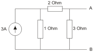
Electric Circuits The thevnin equivalent of the circuit shown in the figure is 0.75 V, 1.5 Ohm 1.5V, 5/6 Ohm 0.75V, 5/6 Ohm 1.5V, 1.5 Ohm 0.75 V, 1.5 Ohm 1.5V, 5/6 Ohm 0.75V, 5/6 Ohm 1.5V, 1.5 Ohm ANSWER DOWNLOAD EXAMIANS APP
Electric Circuits A wire 2.5 m long is bent into a square. An current of 100 A flowing through the wire will produce a magnetizing force at the center of the square, equal to 72 AT / m. 196 AT / m. 222 AT / m. 144 AT / m. 72 AT / m. 196 AT / m. 222 AT / m. 144 AT / m. ANSWER DOWNLOAD EXAMIANS APP
Electric Circuits In RC series circuit R = 2Ω, C = 2μF and 10V dc is applied. Then what is the value of current? 10A 0A 5A 2A 10A 0A 5A 2A ANSWER DOWNLOAD EXAMIANS APP
Electric Circuits Which of the following has least resistivity? Lead. Copper. Aluminium. Mercury. Lead. Copper. Aluminium. Mercury. ANSWER DOWNLOAD EXAMIANS APP
Electric Circuits Kirchhoff’s current law is used for representing a current source. finding equivalent resistance. loop analysis. nodal analysis. representing a current source. finding equivalent resistance. loop analysis. nodal analysis. ANSWER DOWNLOAD EXAMIANS APP
Electric Circuits Among the options which metal has the highest electrical conductivity? Steel. Stranded aluminium. Aluminium. Copper. Steel. Stranded aluminium. Aluminium. Copper. ANSWER DOWNLOAD EXAMIANS APP