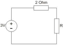
Electric Circuits The maximum power that can be transferred to the load resistor R from the voltage source in the figure is 1 W. 7.5 W. 6/8W. 9/8 W. 1 W. 7.5 W. 6/8W. 9/8 W. ANSWER DOWNLOAD EXAMIANS APP
Electric Circuits A capacitor carries a charge of 0.1 C at 5 V. Its capacitance is 0.2 F 0.02 F 0.05 F 0.5 F 0.2 F 0.02 F 0.05 F 0.5 F ANSWER DOWNLOAD EXAMIANS APP
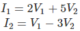
Electric Circuits A two port network is defined by the relation The value of Z11 is -2/11. 2/11. -3. 2. -2/11. 2/11. -3. 2. ANSWER DOWNLOAD EXAMIANS APP
Electric Circuits Kirchhoff’s voltage law is used for nodal analysis. representing a current source. finding equivalent resistance. loop analysis. nodal analysis. representing a current source. finding equivalent resistance. loop analysis. ANSWER DOWNLOAD EXAMIANS APP
Electric Circuits A star connected load has three equal impedance each of (40 + j30) Ω If the line current is 5 A then value of line voltage is 250 √3 V. 250 V. 200 V. 250 / √3 V. 250 √3 V. 250 V. 200 V. 250 / √3 V. ANSWER DOWNLOAD EXAMIANS APP
Electric Circuits Which of the following is not equivalent to watts? Ampere2 – Ohm. Ampere-volts. Amperes/volt. Joules per second. Ampere2 – Ohm. Ampere-volts. Amperes/volt. Joules per second. ANSWER DOWNLOAD EXAMIANS APP