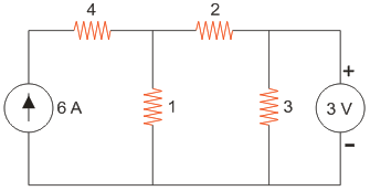
Electric Circuits In the circuit shown in the figure the voltage across the 2 Ω resistor is 2 V. 1 V. 4 V. 3 V. 2 V. 1 V. 4 V. 3 V. ANSWER DOWNLOAD EXAMIANS APP
Electric Circuits The breakdown voltage for paper capacitor is usually 20 to 60 volts. more than 10000 volts. 2000 to 3000 volts. 200 to 1600 volts. 20 to 60 volts. more than 10000 volts. 2000 to 3000 volts. 200 to 1600 volts. ANSWER DOWNLOAD EXAMIANS APP
Electric Circuits In above question, determine the current if E = 100 V, R = 20Ω, R1 = 10 Ω and L = 2 H at 0.5 sec after short circuit. - 6.28. 9.59. 6.98. - 9.59. - 6.28. 9.59. 6.98. - 9.59. ANSWER DOWNLOAD EXAMIANS APP
Electric Circuits A 50 μF capacitor is charged to retain 10 MJ of energy by a constant charging current of 1 A. Determine the voltages across the capacitor? 30 V. 20 V. 60 V. 50 V. 30 V. 20 V. 60 V. 50 V. ANSWER DOWNLOAD EXAMIANS APP
Electric Circuits i) In star connection line current is equal to phase current. ii) In delta connection line voltage is equal to phase voltage. For a given phase connected to the particular line which of the statement is true ? Only (1). Both (1) and (2). None of these. Only (2). Only (1). Both (1) and (2). None of these. Only (2). ANSWER DOWNLOAD EXAMIANS APP
Electric Circuits In parallel RC circuit total current is 5A and current through resistor is 3A. What is the current through capacitor? 3A 2A 4A 5A 3A 2A 4A 5A ANSWER DOWNLOAD EXAMIANS APP